Pусский
 Deutsch
 Français
 Portugues
 Español
 العربية
 lingua italiana
 日本語
日本語 한국어
한국어 Türk dili

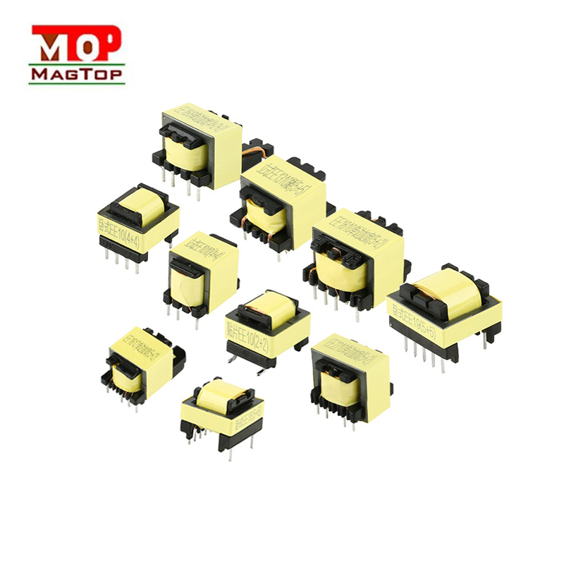
Designing a high-frequency transformer should first start with the magnetic core. The magnetic core of switching power supply transformer is mostly soft magnetic material used under low magnetic field. It has high magnetic permeability, low coercivity and high resistivity. The magnetic permeability is high. When the number of coil turns is certain, it can withstand high external voltage through a small excitation current. Therefore, under the requirement of outputting a certain power, the volume of the magnetic core can be reduced. The core coercivity is low, the hysteresis area is small, and the iron loss is also small. High resistivity means small eddy current and small iron loss. Ferrite material is a composite oxide sintered body with high resistivity and is suitable for use at high frequencies. However, its Bs value is relatively small and is often used in switching power supplies.
High-frequency chain inverter technology uses high-frequency transformers to replace the bulky power frequency transformers in traditional inverters, greatly reducing the size and weight of the inverter. In the hardware circuit design of the high-frequency chain, the high-frequency transformer is an important part.
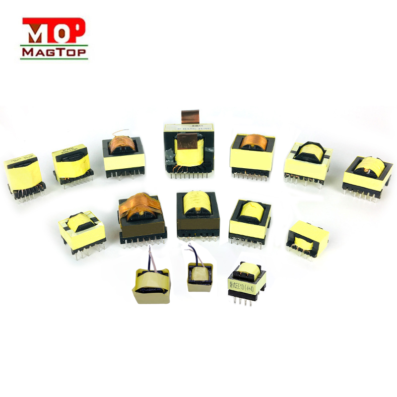
There are usually two methods used in the design of high-frequency transformers [3]: The first is to first find the product AP of the core window area AW and the core effective cross-sectional area Ae (AP=AW×Ae, called the core area product), According to the AP value, look up the table to find the number of the required magnetic material; the second method is to first find the geometric parameters, look up the table to find the core number, and then design.
Notice:
1) In the design, at the maximum output power, the magnetic induction intensity in the magnetic core should not reach saturation to avoid distortion when the signal is large.
2) During the transient process, high-frequency chain leakage inductance and distributed capacitance will cause surge currents, peak voltages and pulse top oscillations, which will increase losses and, in severe cases, cause damage to the switch tube. At the same time, when the output winding has many turns and layers, the influence of distributed capacitance should be considered. Reducing the distributed capacitance will help suppress the interference of high-frequency signals to the load. It is difficult to reduce distributed capacitance and leakage inductance at the same time for the same transformer. Appropriate capacitance and inductance should be ensured according to different working requirements.
1) In the design, at the maximum output power, the magnetic induction intensity in the magnetic core should not reach saturation to avoid distortion when the signal is large.
2) During the transient process, high-frequency chain leakage inductance and distributed capacitance will cause surge currents, peak voltages and pulse top oscillations, which will increase losses and, in severe cases, cause damage to the switch tube. At the same time, when the output winding has many turns and layers, the influence of distributed capacitance should be considered. Reducing the distributed capacitance will help suppress the interference of high-frequency signals to the load. It is difficult to reduce distributed capacitance and leakage inductance at the same time for the same transformer. Appropriate capacitance and inductance should be ensured according to different working requirements.